Grad Cap Light Display
a custom circuit board with 100 rgb leds
May 2020
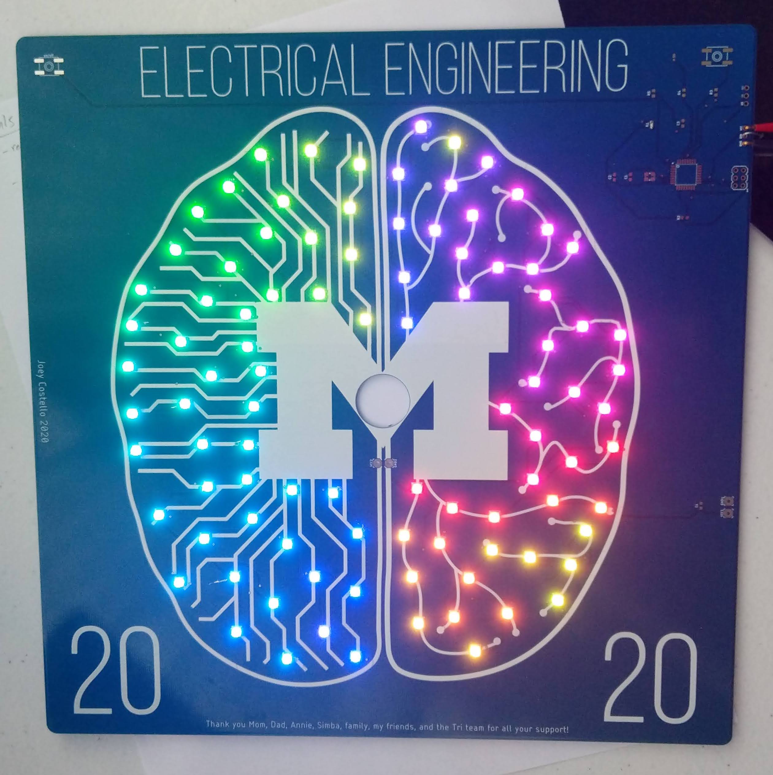
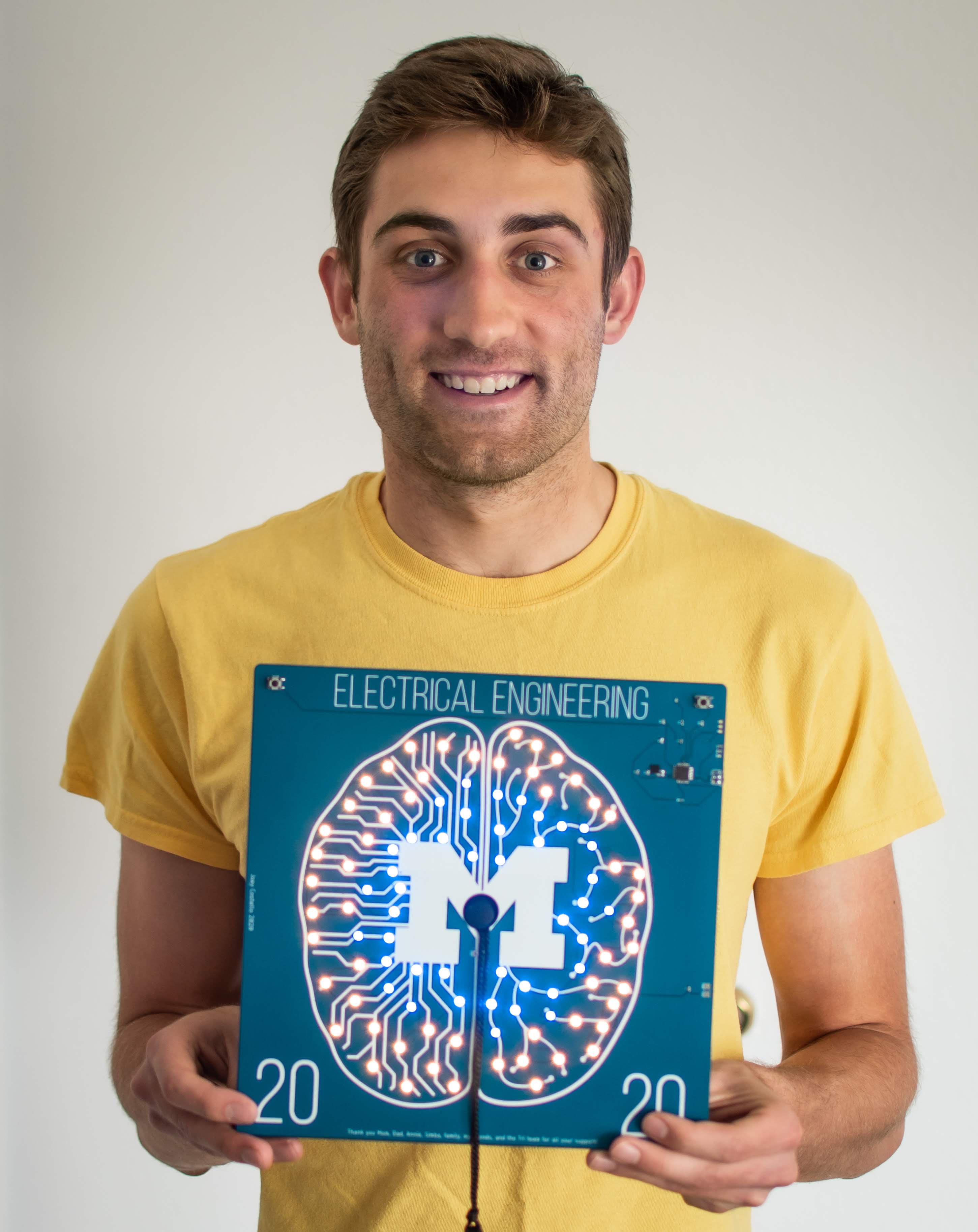
Back in February, I started designing a light-up graduation cap for my undergrad graduation ceremony scheduled for May (ultimately cancelled because of the pandemic). As an electrical engineer and soon-to-be neuroengineering grad student, I took inspiration from circuit-brain designs like this . Others have put LED matrix displays on their grad cap and programmed cool animations across the screen. But this seemed too easy and all designs disappeared as soon as it turned off. I wanted something that could light up with animations, but also have a permanent design for display. I settled on creating a custom circuit board with small LEDs animating a printed design.
Designing the board
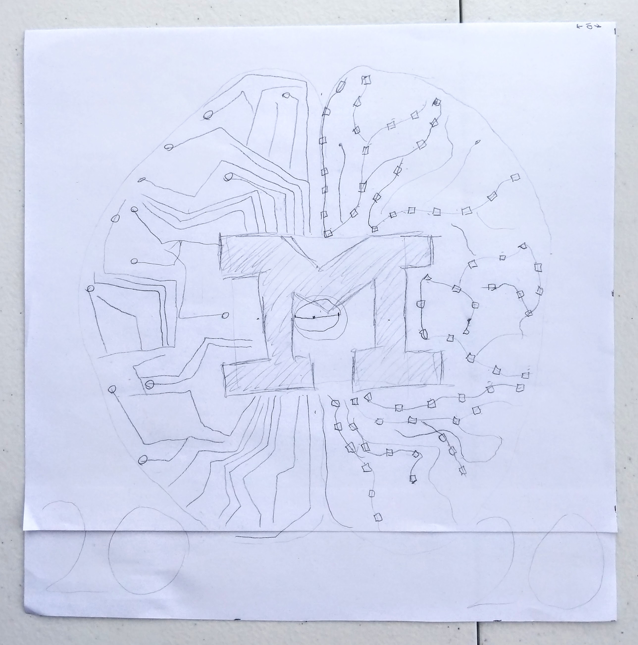
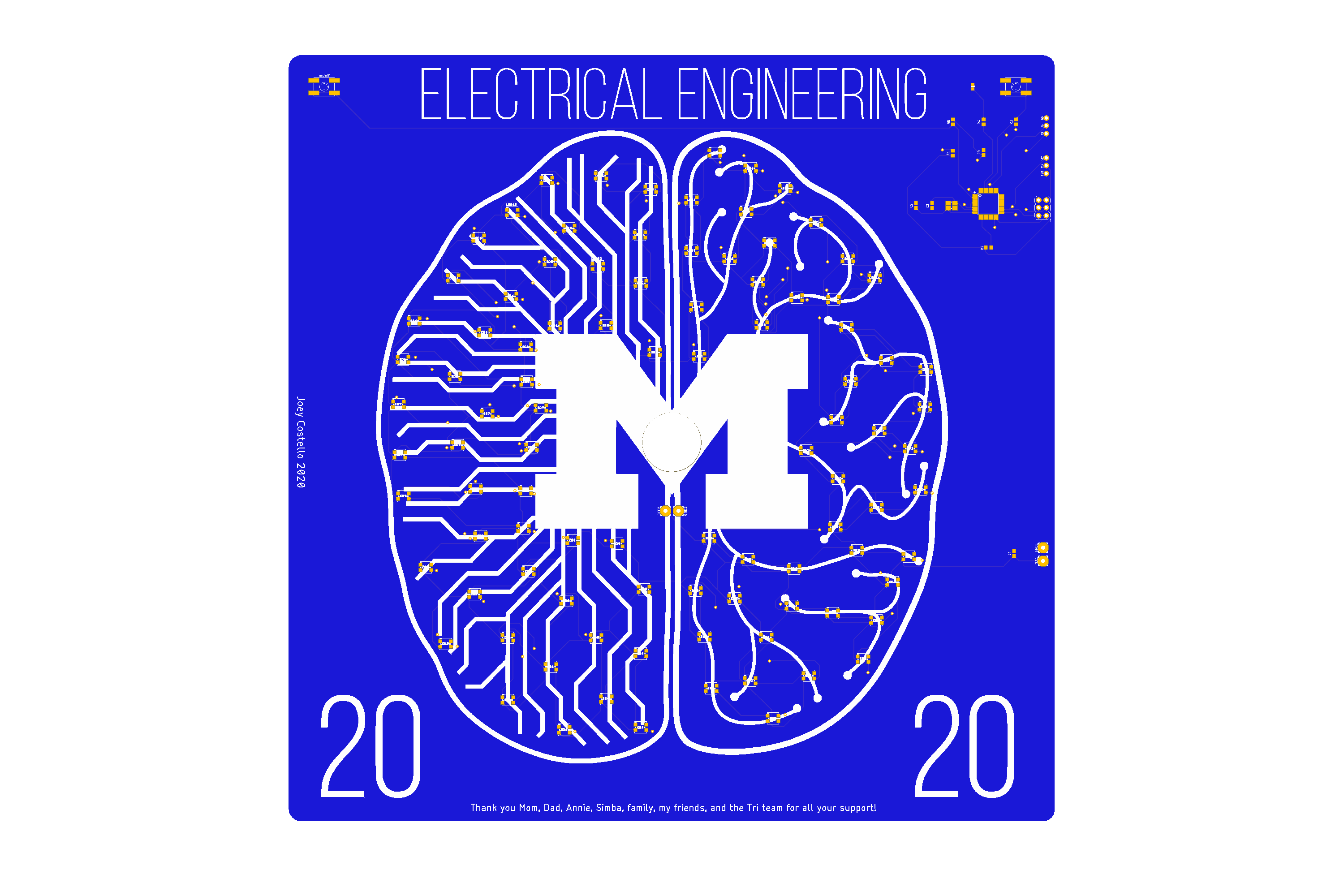
After drawing a few sketches including a full-size drawing, I created the design in Photoshop. The mortarboard has an inconvenient 0.75in hole for the tassel so I made sure it was centered nicely within the M. I exported the design as an SVG and imported into Eagle.
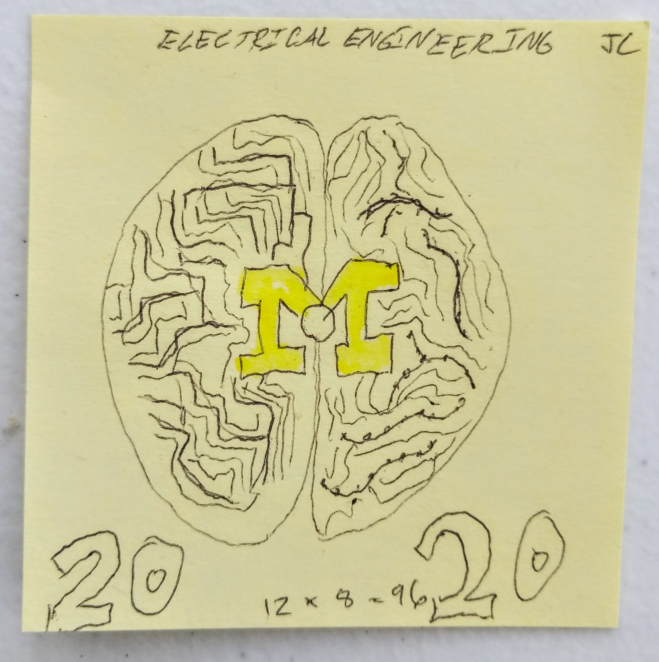
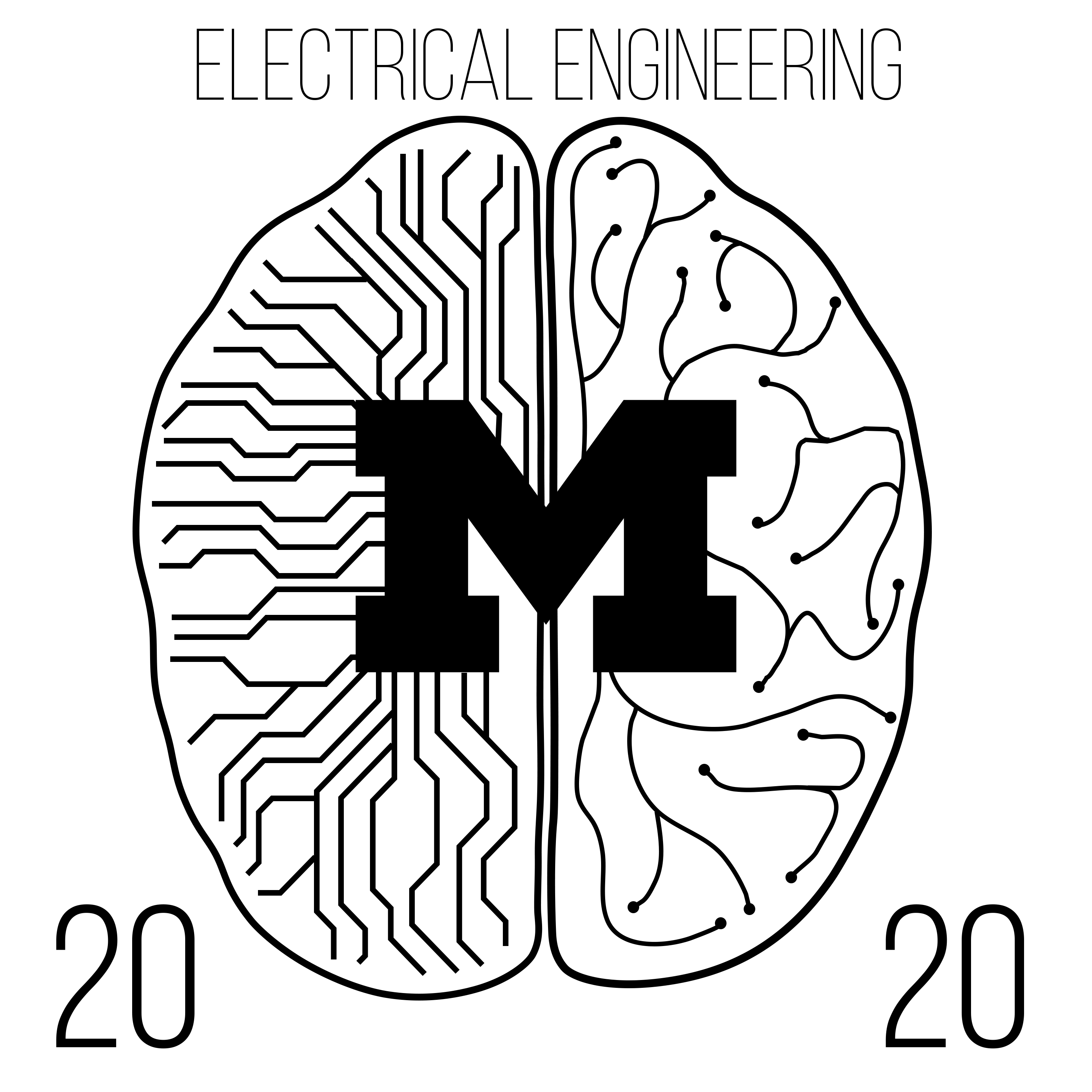
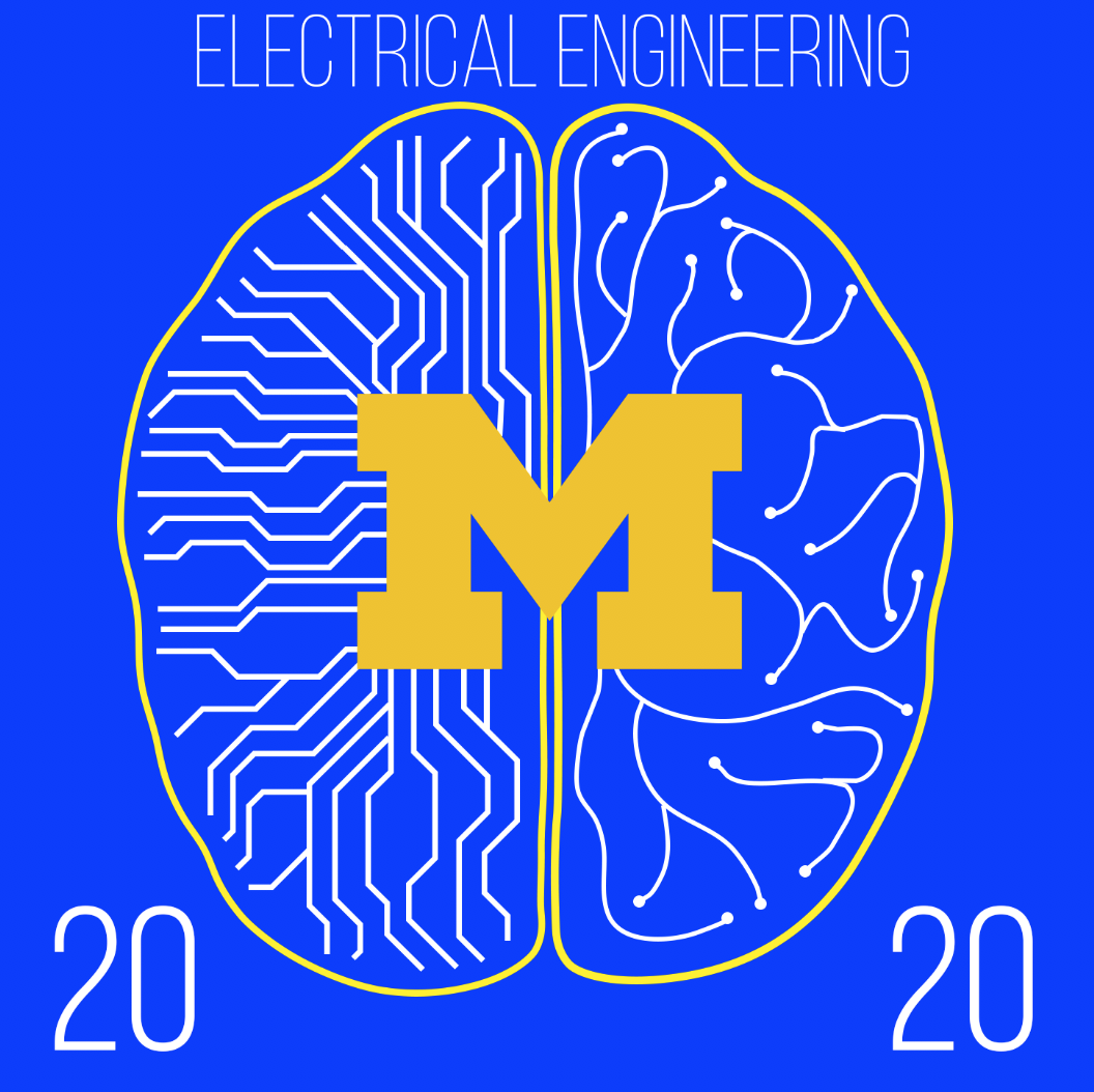
I chose to use WS2812b RGB leds, which are commonly used in LED light strips. I went with the 3.5mm SMD LEDs which were the smallest I could reliably hand-solder (for future board iterations I may try the 1.5mm LEDs for a higher resolution display). The LEDs are chained together and only need a single data line for control, making it very easy to created individually-addressable displays with a few lines of code. I ended up using 96 LEDs evenly spaced around the board to animate the “neural activity”.
For the microcontroller I chose the Atmel328p, the same as on the Arduino Uno, allowing for compatibility with the standard Arduino IDE. A small lipo battery would power the board and fit on the underside of the grad cap, hidden from view.
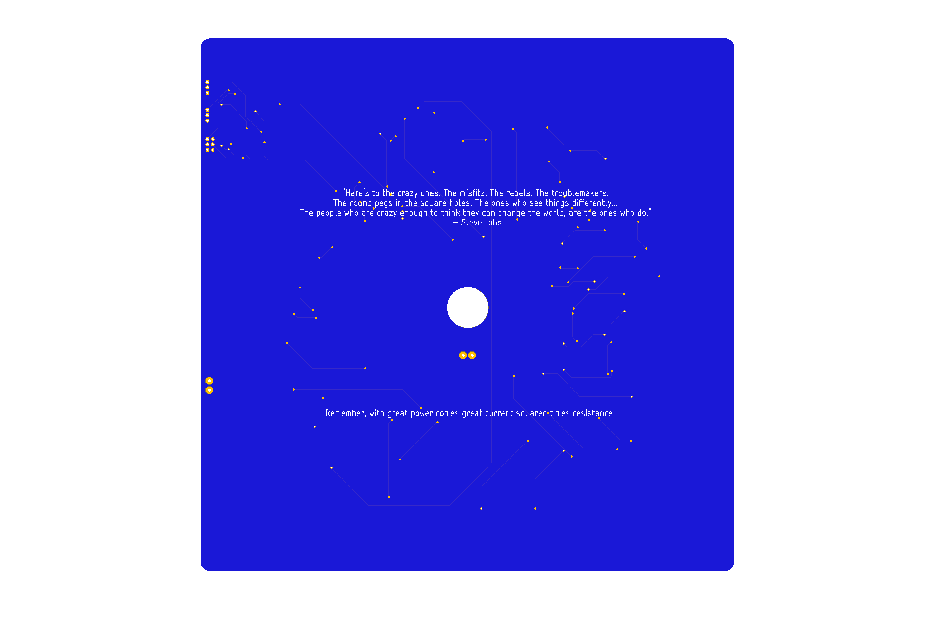
I created the schematic and laid out the full board in Eagle. I added a pin header to program the microcontroller and breakout connections to manually control the LEDs (which were very useful when the microcontroller wasn’t working).
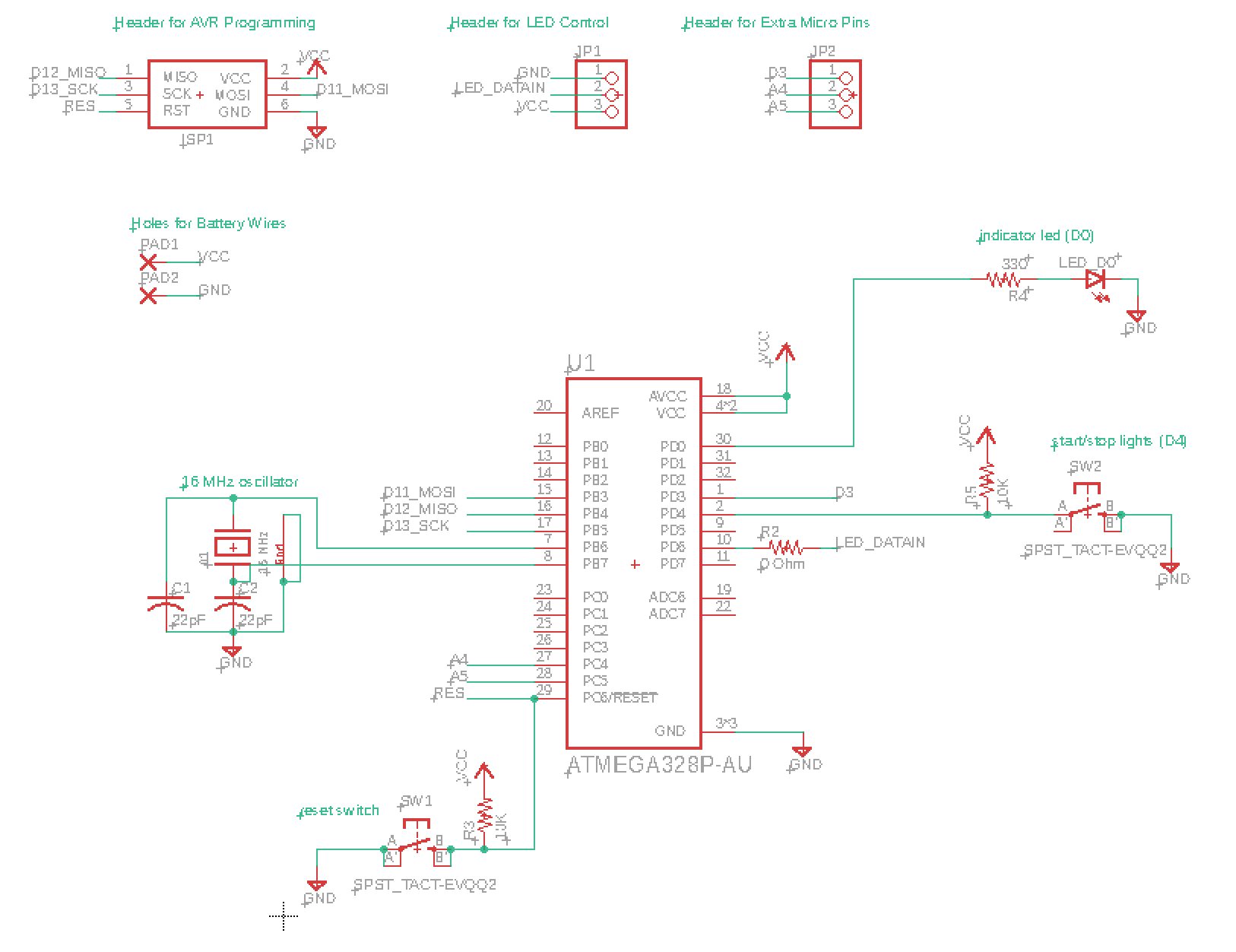
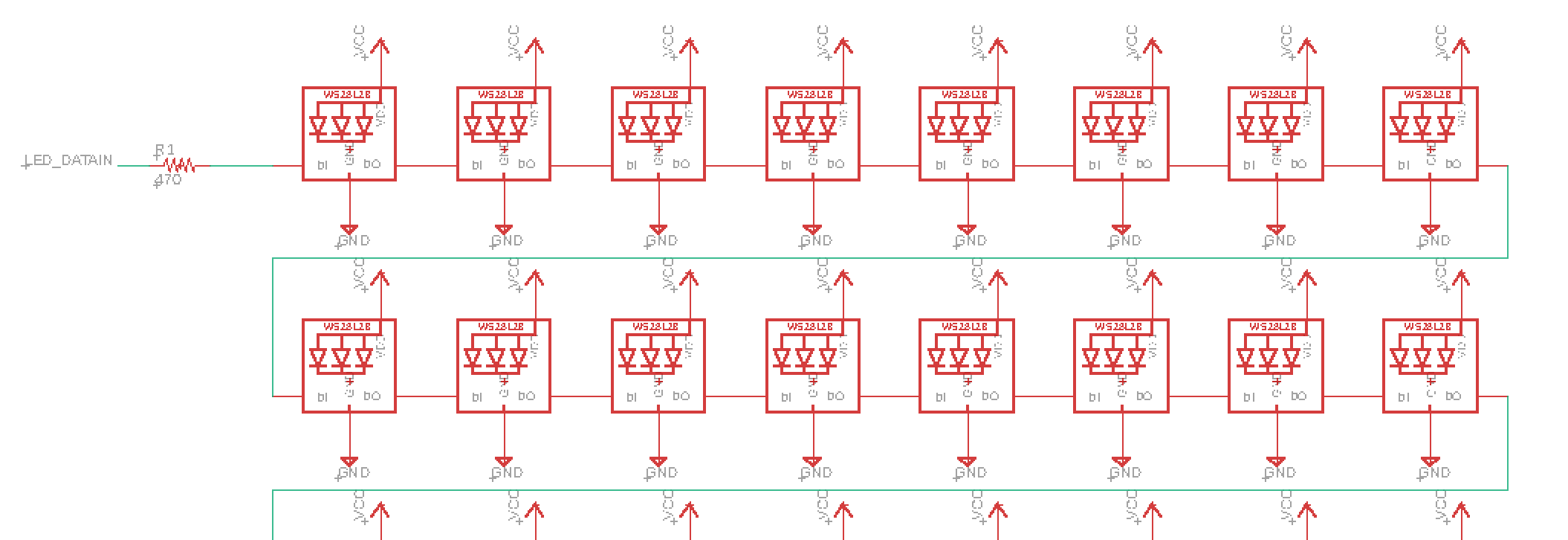
After finalizing the PCB design, the next challenge was finding a manufacturer to make it for a reasonable price. OSHPark and a couple others would charge almost $500 for the 100in2 board. I went with JLCPCB who produced the 5 copies of the full board with faster shipping for $52. Even in mid-March with Covid in full-swing in China, the boards arrived in only a couple weeks.
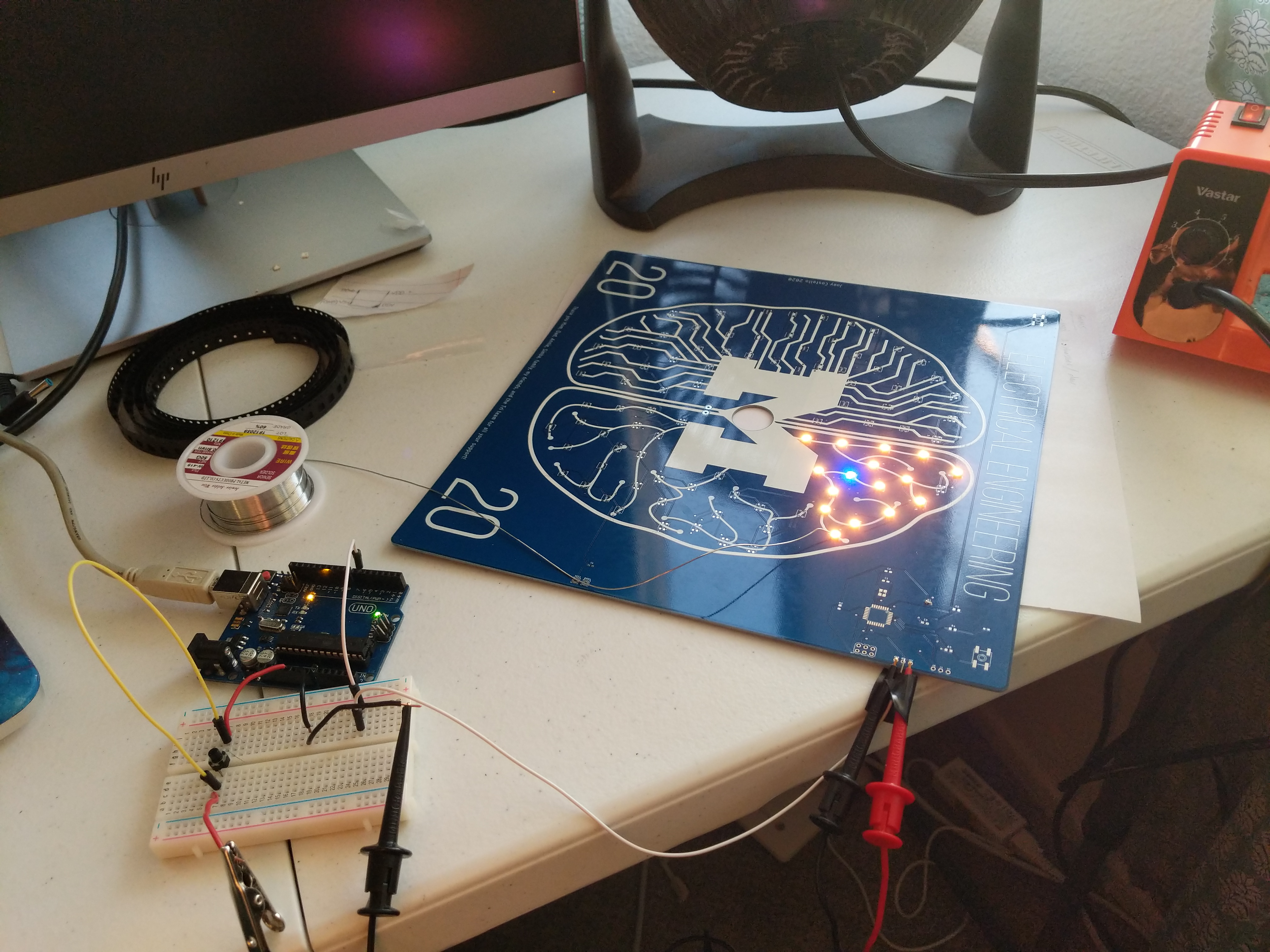
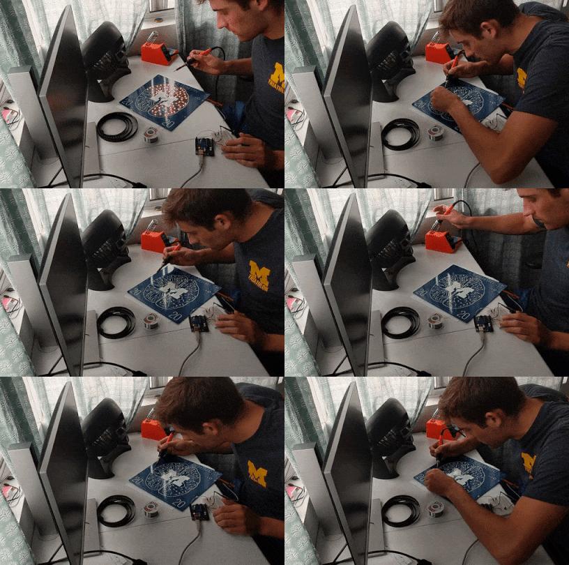
Once the boards and all components arrived, I got started on the 450+ solder connections. I connected an external Arduino to the LED input pins and verified the connections each time I added another LED. The main problem with using only a single data-line for all the LEDs is if a single connection is bad, then the whole string of lights fails (but it’s obvious where the bad connection lies).
Programming animations
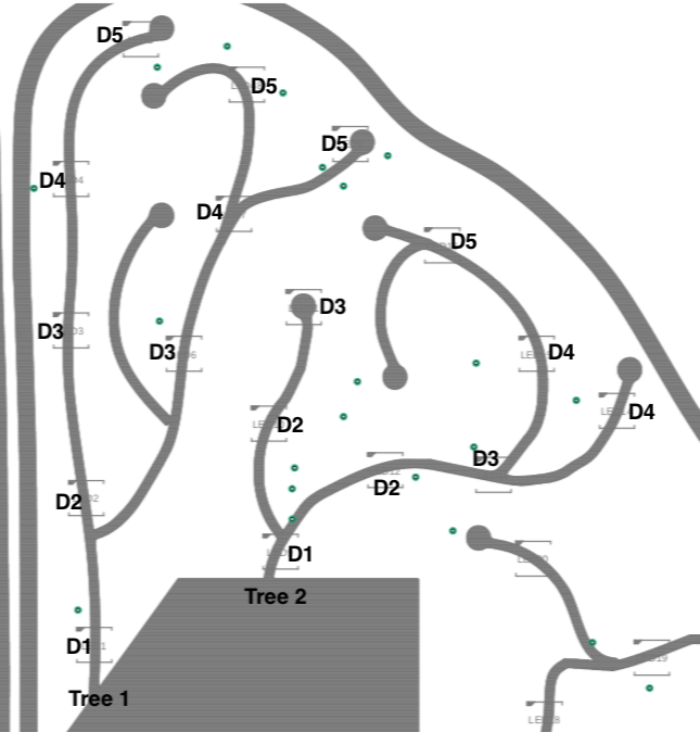
Now the fun part: programming the light animations. Adafruit’s Neopixel library made it easy to set each LED’s color and brightness. The main challenge was that the LEDs weren’t in a convient grid, but rather scattered randomly around the board. To solve this, I recorded each LED’s XY coordinates and it’s “neural tree” location (tree number and depth, see figure below), and stored these in an array. For simple animations like the exploding wave, an LED’s color is calculated based on its location and the current timestep. For the neural activity animation, each “tree” is activated at a random time, with maximal activation starting at depth 1 and flowing up to depth 5 smoothly.
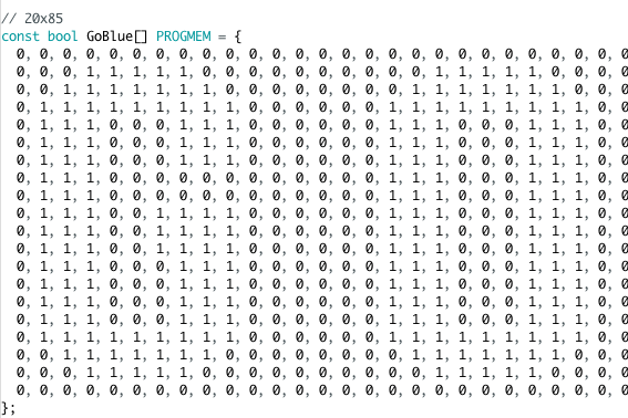
But what’s a Michigan cap without a Go Blue? I converted the G O B L U E text into a 20x85 bitmap that scrolls across the display. At a single timestep, a 20x20 slice is taken out of the full bitmap. Each LED’s color is determined by rounding its XY position to the nearest 20x20 grid location, then extracting the 1/0 at the location in the current 20x20 slice. Iterating slices across the full 85 width shows the full GOBLUE.
I hot-glued the PCB onto the mortarboard with the battery on the underside. I have yet test the battery life, but I expect it to give at least an hour of display time.
The display turned out exactly how I’d pictured it and I hope I can wear it to a ceremony in the future. There are many more possibilities for animations, especially since it’s a full-color display (not limited solely to maize and blue). I’m now working on making a wooden frame to display it on a wall when not being worn. An additional future project might involve placing EEG electrodes inside the cap to display real brain activity with the lights. Perhaps that’s a project for my PhD graduation cap.
